Luis Pineda
Monday, January 5, 2026
VPN fortigate - OPNSense behind NAT
Overview
In this article, I document the process of building a site-to-site IPsec VPN between a FortiGate firewall with a public IP address and an OPNsense firewall located behind NAT.
This scenario is common in real-world environments where one side of the tunnel is hosted behind an ISP router or does not have a stable public IP address. The configuration shown here works reliably by combining IKEv2, pre-shared keys, and Peer ID–based authentication.
The setup uses OPNsense 25.7.10, which is important because this version relies on the newer IPsec Connections framework rather than the legacy IPsec model.
A video walkthrough of this configuration is available on YouTube. This post serves as a written reference and summary, including the reasoning behind key design choices.
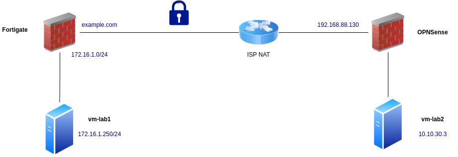
Network Topology
On the FortiGate side, the internal network is:
172.16.1.0/24- Test host:
172.16.1.250
The FortiGate has a public-facing WAN interface. In this documentation, a DNS alias (example.com) is used instead of exposing the real public IP address. Some screenshots in the video are intentionally blurred for this reason, but all relevant configuration steps remain visible.
On the OPNsense side, the firewall is located behind an ISP NAT router:
- Internal network:
10.10.30.0/24 - Test host inside this network
Because OPNsense does not have a directly reachable public IP, the VPN must be initiated from this side, and peer identification cannot rely on source IP addresses alone.
FortiGate Configuration
Creating the IPsec Tunnel
Navigate to:
VPN → IPsec Tunnels → Create New
- Tunnel name:
VPN_Demo - Configuration type: Custom
- Remote Gateway: Dialup User
- Interface: WAN interface used for VPN
The Dialup User option is required because the OPNsense peer is behind NAT and does not have a fixed public IP address.
Authentication Settings
- IKE Version: IKEv2
- Peer Options: Specific Peer ID
- Peer ID:
cats.net - Authentication Method: Pre-shared Key
Use a strong pre-shared key. This same key will later be configured on the OPNsense side.
Phase 1 Proposal
To keep the configuration simple and secure, use a single proposal:
- Encryption: AES-256
- Authentication: SHA-256
- Diffie-Hellman Group: 14
- Local ID:
dogs.net
Phase 2 Configuration
This phase defines which networks will be routed through the tunnel.
- Local Network:
172.16.1.0/24 - Remote Network:
10.10.30.0/24
Advanced settings:
- Encryption: AES-256
- Authentication: SHA-256
- Diffie-Hellman Group: 14
If you want to do it in cli commands:
# --- Phase 1 (IKE) ---
config vpn ipsec phase1-interface
  edit "VPN_Demo"
    set interface "<WAN_INTERFACE>"          # e.g. "wan1"
    set ike-version 2
    set peertype any                        # dialup
    set net-device disable
    set mode aggressive                      # often used with dialup/ID
    set proposal aes256-sha256
    set dhgrp 14
    set remote-gw 0.0.0.0                    # dialup
    set psksecret "<STRONG_PSK>"
    set localid "dogs.net"
    set peerid "cats.net"
  next
end

# --- Phase 2 (IPsec/ESP) ---
config vpn ipsec phase2-interface
  edit "VPN_Demo_p2"
    set phase1name "VPN_Demo"
    set proposal aes256-sha256
    set dhgrp 14
    set src-subnet 172.16.1.0 255.255.255.0
    set dst-subnet 10.10.30.0 255.255.255.0
  next
end
Static Route
Create a static route so the FortiGate knows how to reach the remote network.
Network → Static Routes → Create New
- Destination:
10.10.30.0/24 - Interface: the IPsec tunnel interface
Fortigate commands:
# --- Static route to remote LAN via IPsec ---
config router static
  edit 0
    set dst 10.10.30.0 255.255.255.0
    set device "VPN_Demo"
  next
end
Firewall Policies
Create an address object for the remote network:
Firewall → Addresses
- Name:
VPN_Demo_LAN - Network:
10.10.30.0/24
# --- Address object for remote network ---
config firewall address
  edit "VPN_Demo_LAN"
    set subnet 10.10.30.0 255.255.255.0
  next
end
Then create two firewall rules:
Outbound Rule
- Incoming Interface: ISP/WAN
- Outgoing Interface: LAN
- Source: Local LAN
- Destination:
VPN_Demo_LAN - Service: ALL
- NAT: Disabled
Return Rule
- Incoming Interface: IPsec tunnel
- Outgoing Interface: ISP/WAN
- Source/Destination: reversed
- NAT: Disabled
# --- Firewall policies (NAT disabled) ---
# Policy: LAN -> VPN
config firewall policy
  edit 0
    set name "To_VPN_Demo"
    set srcintf "<LAN_INTERFACE>"            # e.g. "lan"
    set dstintf "VPN_Demo"
    set srcaddr "<LOCAL_LAN_ADDR_OBJ>"       # or "all" if you prefer
    set dstaddr "VPN_Demo_LAN"
    set action accept
    set schedule "always"
    set service "ALL"
    set nat disable
  next
end

# Policy: VPN -> LAN (return traffic)
config firewall policy
  edit 0
    set name "From_VPN_Demo"
    set srcintf "VPN_Demo"
    set dstintf "<LAN_INTERFACE>"
    set srcaddr "VPN_Demo_LAN"
    set dstaddr "<LOCAL_LAN_ADDR_OBJ>"       # or "all"
    set action accept
    set schedule "always"
    set service "ALL"
    set nat disable
  next
end
At this point, the FortiGate configuration is complete.
OPNsense Configuration
Before configuring OPNsense, verify that connectivity is currently failing. This confirms that traffic is not leaking and that the VPN is not already active.
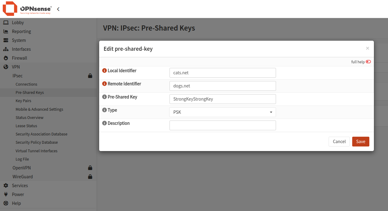
Pre-Shared Key Configuration
Navigate to: VPN → IPsec → Pre-Shared Keys
Create a new key:
- Local ID:
cats.net - Remote ID:
dogs.net - Pre-shared key: same as on FortiGate
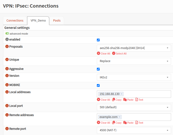
Creating the IPsec Connection
Go to: VPN → IPsec → Connections → Add
General Settings
- IKE Version: IKEv2
- Proposals: AES-256 / SHA-256
- Local Address: OPNsense WAN IP (private is fine)
- Remote Address: FortiGate public IP or DNS name (e.g.
example.lab) - Aggressive Mode: Enabled
- Unique: Replace
Authentication
Under Local Authentication:
- Local: shared key associated with
cats.net - Remote: shared key associated with
dogs.net
Phase 2 (Child SA)
- DPD Mode: Start
- ESP Proposal: AES-256 / SHA-256
- Local Network:
10.10.30.0/24 - Remote Network:
172.16.1.0/24
Save and apply the configuration.
Verification
Once both sides are configured, verify tunnel status.
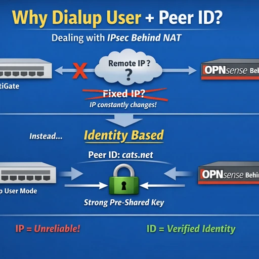
Why Dialup User and Peer ID Matter
When one side of an IPsec tunnel is behind NAT, IP-based peer identification breaks down. The public source IP may change or be unknown entirely.
Using Dialup User allows the FortiGate to accept incoming IPsec connections from peers with dynamic or unknown IP addresses.
Security is preserved through Peer ID–based authentication:
- The peer proves its identity using a hostname-style identifier
- The identifier must match on both sides
- The pre-shared key must also match
In short:
NAT breaks IP-based identification.
Peer IDs restore secure identity verification.